
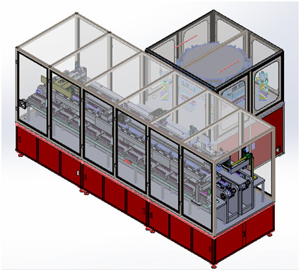


Automatic Liquid Injection Machine For 3200F Cylindrical Supercapacitor
equipment introduction
The equipment is suitable for manual feeding box of round aluminum shell supercapacitor, the equipment automatically grabs the supercapacitor, automatically sweeps the bar code, automatically weighs, automatically locates the liquid injection hole, automatically turns the plate to feed, automatically fills the liquid, automatically vacuums to rest, automatically weighs the second time, and automatically cuts the material.
2. Technical parameters:
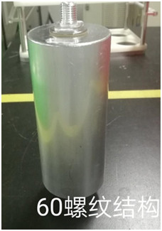
2.1. Size of supercapacitor:
| Supercapacitor model | Diameter (mm) | H(mm) | H1(pole column) (mm) | M(pole thread (mm) |
| 60162 | 60 | 162 |
2.1 vacuum sampling and then liquid injection, one-time liquid injection, liquid injection after the vacuum and pressure alternate static mode, good absorption consistency, good uniformity, high efficiency, high precision, easy and reliable operation; 6 ultracapacitors on a liquid injection tray and 8 station rotary table can vacuum and pressurize 48 ultracapacitors. The standing time can be set.
2.2 liquid injection process:
Manual feeding box → manipulator automatically grabs 6 supercapacitors to the small tray → supercapacitor automatically rotates to sweep the bar code → put them into the electronic scale fixture to weigh the supercapacitor before liquid injection → manipulator clips the supercapacitor into the liquid injection tray → servo motor turns the supercapacitor. Automatically detect liquid injection port and correcting fluid injection port location - clip manipulator automatically small tray into the wheel - automatic injection pump to the super capacitor filler - automatic pumping air into vacuum state, let stand absorption (liquid injection station) - > note liquid tray after eight times let stand out automatically to let stand manipulator automatically remove super capacitor after weighing (unqualified supercapacitor artificial rehydration) - > note liquid tray automatically return is the highest position for the next cycle weighting, liquid injection, vacuum let stand, weighing again.
2.3 features:
2.3.1 use separate supercapacitor to automatically pressurize and vacuum.
2.3.2 closed vacuum pumping and pressurization is adopted to prevent the electrolyte of the supercapacitor from being pumped out in large quantities, reduce the number of times of second liquid injection, and protect the vacuum pump from corrosion.
2.3.3 the vacuum tank adopts a unique cooling structure design. The electrolytic liquid cooled through the vacuum tank is condensed at the bottom of the tank to protect the vacuum pump.
2.3. Automatic weighing and pulling belt system: automatic bracket flow pulling belt, automatic weighing of supercapacitor, weighing computer and data processing, database, NG alarm and other functions.
3. Basic parameters:
|
Machine specifications project |
ZDAE07C |
| The efficiency of | 12PPM (the efficiency is calculated in 2 minutes according to the vacuum pumping time) |
| Precision injection fluid | Within + / - 2 g |
| Let stand time | Calculated according to 2min. |
| The yield | The qualified rate of one injection is 98% of >, and the unqualified supercapacitor adopts manual replenisher. |
| Liquid injection rate | 180 ~ 300 g is adjustable |
| power | 5KW |
| Precision of electronic scale | Range: 5Kg, accuracy ±0.1g. |
| Equipment failure rate | 5% or less |
| sealing | The liquid injection station is in the sealed state, and the vacuum is pumped to -95kpa, which can be maintained for 2min) |
| Overall size (mm) | 4500*3000*1800 |
3.2.1. Manually put the whole box of ultracapacitors into the feeding vacancy.
3.2.2. The manipulator takes the supercapacitor from the material box, sweeps the bar code and puts it into the weighing station;
3.2.3. Electronic weighing, the device will automatically read the bar code and weighing data into the computer;
3.2.4. The manipulator will automatically remove the weighing supercapacitor and put it into the sub-tray. There are 6 supercapacitors in one sub-tray.
3.2.5. The cylinder drives the passive wheel to press the ultracapacitor, the active drive wheel to press the ultracapacitor, the servo motor turns the ultracapacitor, and the optical fiber detects the liquid injection port and stops. After detecting 6 in turn, the manipulator automatically grabs the sub-tray and puts it into the mother tray.
3.2.5. The rotary automatic feeding mechanism can automatically feed the small tray and at the same time automatically unload the small tray supercapacitor filled with liquid.
3.2.6. The automatic liquid injection machine works, the servo motor drives the liquid injection nozzle to move, and 6 supercapacitors are injected successively.
3.2.7. Vacuum pumping: the time is set by the touch screen.
3.2.8. Automatic liquid injection: 3 double-head liquid injection pumps.
3.2.9. Standing: alternate between pressure and low vacuum.
3.2.10. Automatic downforce: help to separate the supercapacitor from the injection nozzle.
3.2.11. Remove the bracket, put on the new unfilled bracket, and repeat the operation flow of items 7 to 11. The liquid-filled supercapacitor bracket moves forward;
3.2.12. Weigh again. The ultracapacitor bracket is moved to the reweighing station after pulling belt A, the code reader reads the bar code of the bracket, and the manipulator moves the six ultracapacitors to the weighing sensor in turn, weighs them, and reads the bar code and weighing data into the computer. The computer automatically calculates the amount of liquid injected into the supercapacitor and tells whether the amount of liquid injected into the supercapacitor is qualified or not. NG will have an immediate alarm, and the supercapacitor of NG will be automatically excluded.
3.2.13. When the bracket reaches the right end of the B pull belt, the manipulator automatically grabs the supercapacitor to the original feeding box; Corresponds to the material box.
3.2.14. The empty bracket shall be carried by the manipulator 1 to pull belt A, and the bracket shall flow back from right to left;
3.2.15. At the leftmost end of belt B, the manipulator moves the bracket to belt A for the next cycle.
Note: vacuum time and static time can be set according to the situation. Pressure static or atmospheric static can be selected
3.3 equipment configuration
| sequence | Name of the device | unit | The number of | note |
| 1 | Station 8 automatic injection machine | Taiwan | 1 | |
| 2 | Electric injection pump | Taiwan | 3 | Accuracy of + - 0.5% |
| 3 | Vacuum pipe | Taiwan | 2 | The manufacturer should bring along their own |
| 4 | Bracket, | a | 24 | |
| 5 | Control system | Set of | 1 | |
| 6 | Cleaning system | Set of | 1 | |
| 7 | Electrolyte transfer tank | Set of | 1 | |
| 8 | Cleaning solvent tank | Set of | 1 | |
| 9 | Cleaning solvent tank | Set of | 1 | |
| 10 | housing | Set of | 1 | |
| 11 | Drawstring system | Set of | 2 | |
| 12 | Weighing system | Set of | 4 | |
| 13 | Manipulator system | Set of | 6 | |
| 14 | Vacuum pump | a | 1 | |
| 15 | Automatic code reading and weighing system | Set of | 1 | |
| 16 | Control system | Set of | 1 | Omron PLC |
| Remark: | ||||
3.4. Equipment color: color: color card: gsb05-1426-2001 (instead of GSB g51001-94),61 R02 vermillion, to ask for mirror paint, smooth surface without spots, no concave and convex pits.
4. Site environmental requirements
4.1. Ambient temperature: shall be determined by the factory environment of party a;
4.2. Relative humidity: dry air shall be provided by party a;
4.3 power supply: three-phase 380V, 50HZ, voltage fluctuation range: + 10%-10%;
4.4. Compressed air: after being dried, filtered and stabilized, the outlet air pressure is greater than 5.0kg/cm2;
4.5. Vacuum source: vacuum pump or pipeline vacuum, vacuum degree greater than -98kpa;
4.6 party a shall ensure that the air on the site is unimpeded;
1. New equipment promise
Our company guarantees that the goods provided to customers are brand new, complete and unused equipment.
2. Confidentiality commitment
Our company promises that without the written permission of any party, the other party's related drawings, technical information, business information and other business secrets and technical secrets must not be leaked to third parties in any way.
3. After-sales service commitment
(1) Two months from the date of shipment of the equipment, Party B is responsible for non-human faults in a timely and free warranty within one year (when the equipment is faulty, the after-sales service staff will respond within 2 hours after receiving the notification. According to the situation, personnel must be in place within 48 hours. No later than 60 hours, to ensure the continuity of production by the buyer;
(2) After the equipment has passed the warranty period, if there is a problem, the two parties communicate and deal with it. If necessary, after-sales personnel will be sent to repair it, and only the cost will be charged. Zh
(3) During the warranty period stipulated in the contract and technical agreement signed by the two parties, the company will provide a warranty for quality problems that are not caused by human damage during the normal use of our products.


